1
Open the drawing and an empty Revit project
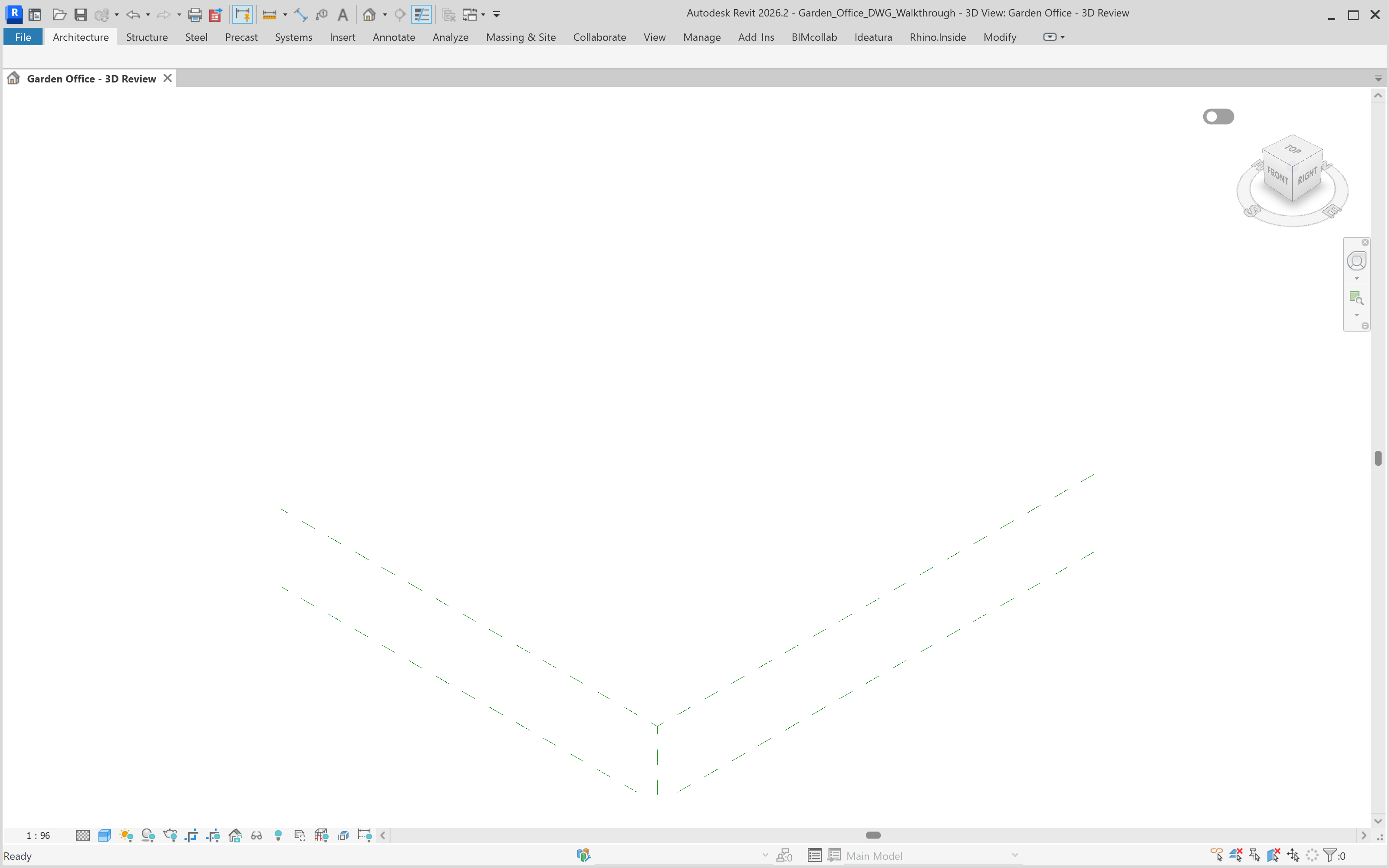
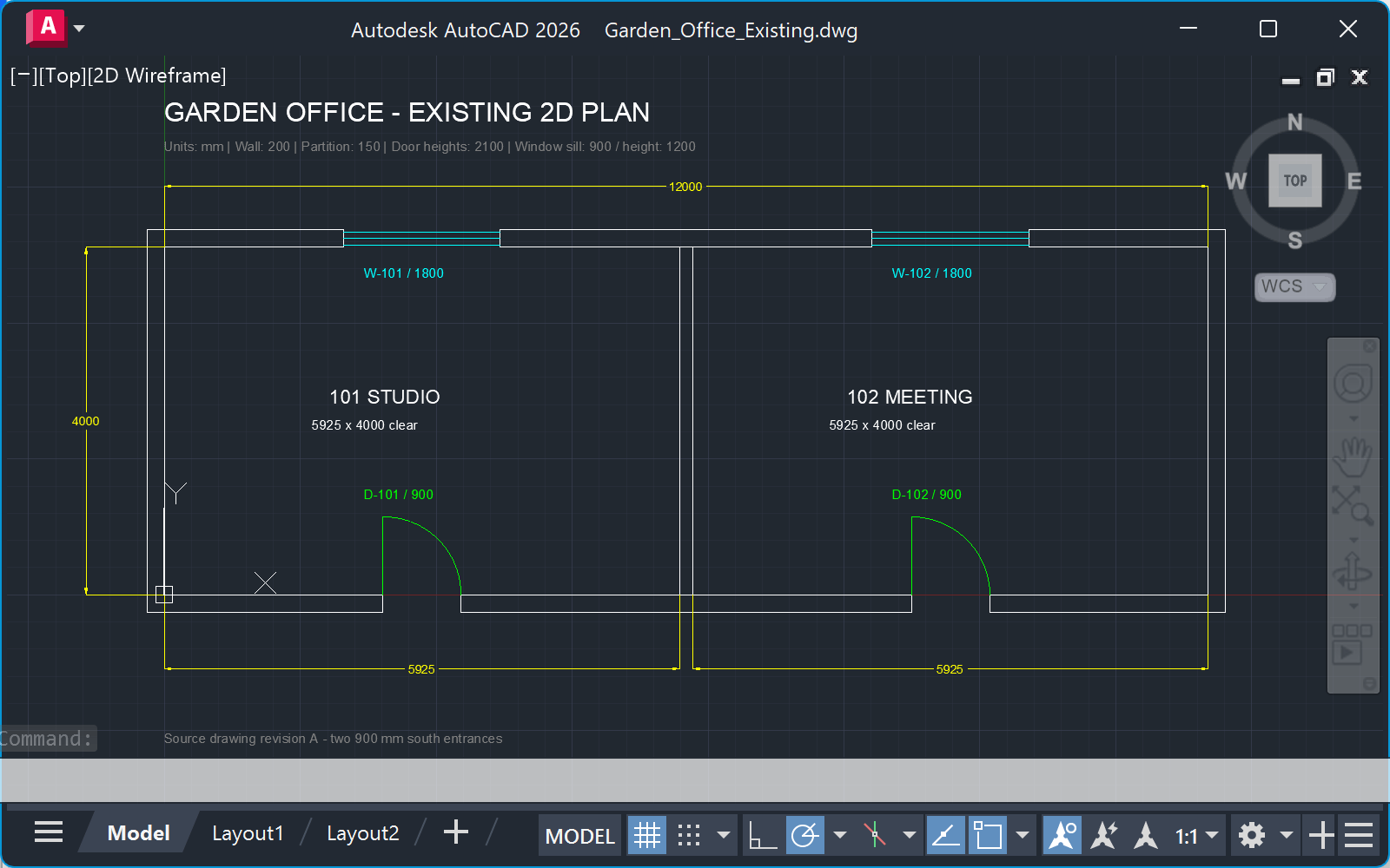
Download the example DWG and open it in AutoCAD. Open an empty destination project in Revit. This measured drawing describes a two-room, single-storey office. We will reconstruct its walls, floor, doors and windows as editable Revit elements while keeping the DWG unchanged.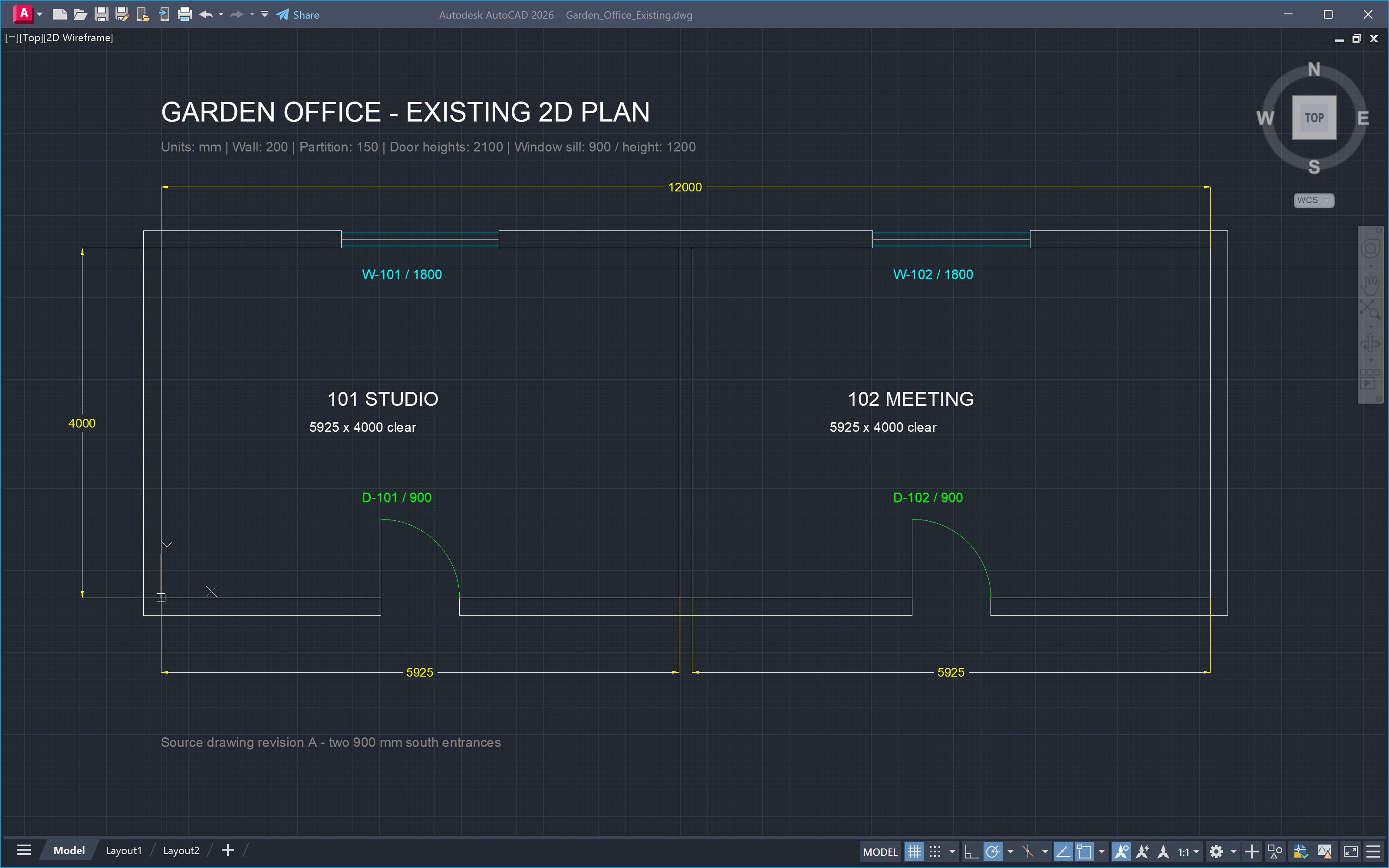
2
Connect AutoCAD and Revit
Start a new conversation in Studio. Open Connected Apps and select both the source AutoCAD drawing and the destination Revit project. Check their filenames before continuing.One conversation can work across both selected applications: read the source in AutoCAD and create elements in Revit.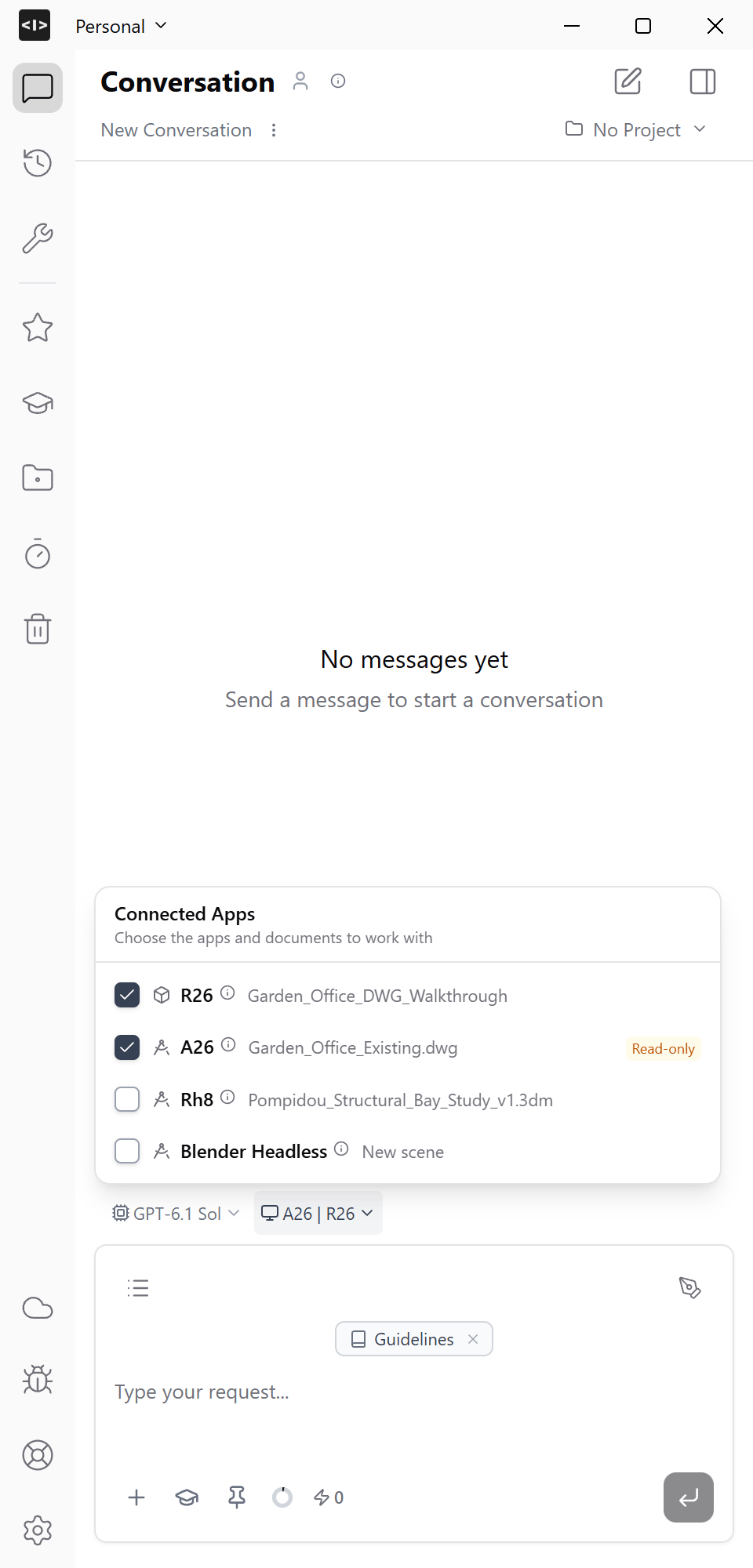
3
Review the modelling skill
This walkthrough uses a skill named DWG to Revit. If it is not in your workspace, create a skill using the instructions from this example.Open Skills and select DWG to Revit. Read its instructions in the preview. The skill explains how to read drawing geometry, interpret walls and openings, handle missing information and check the result.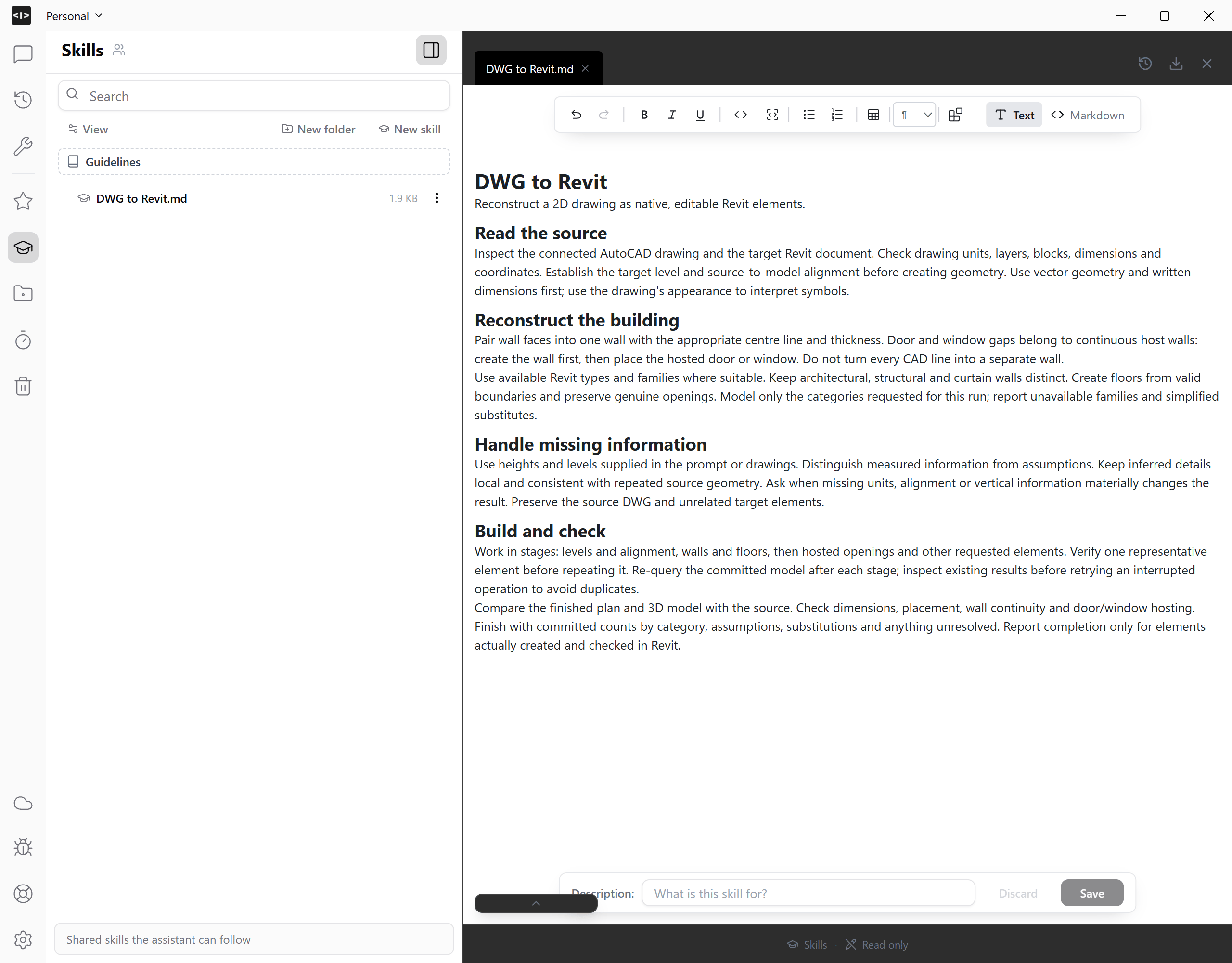
4
Attach the skill and ask for the conversion
Return to the conversation. Open the skill picker and attach DWG to Revit. Confirm that AutoCAD and Revit are still selected, then enter your request.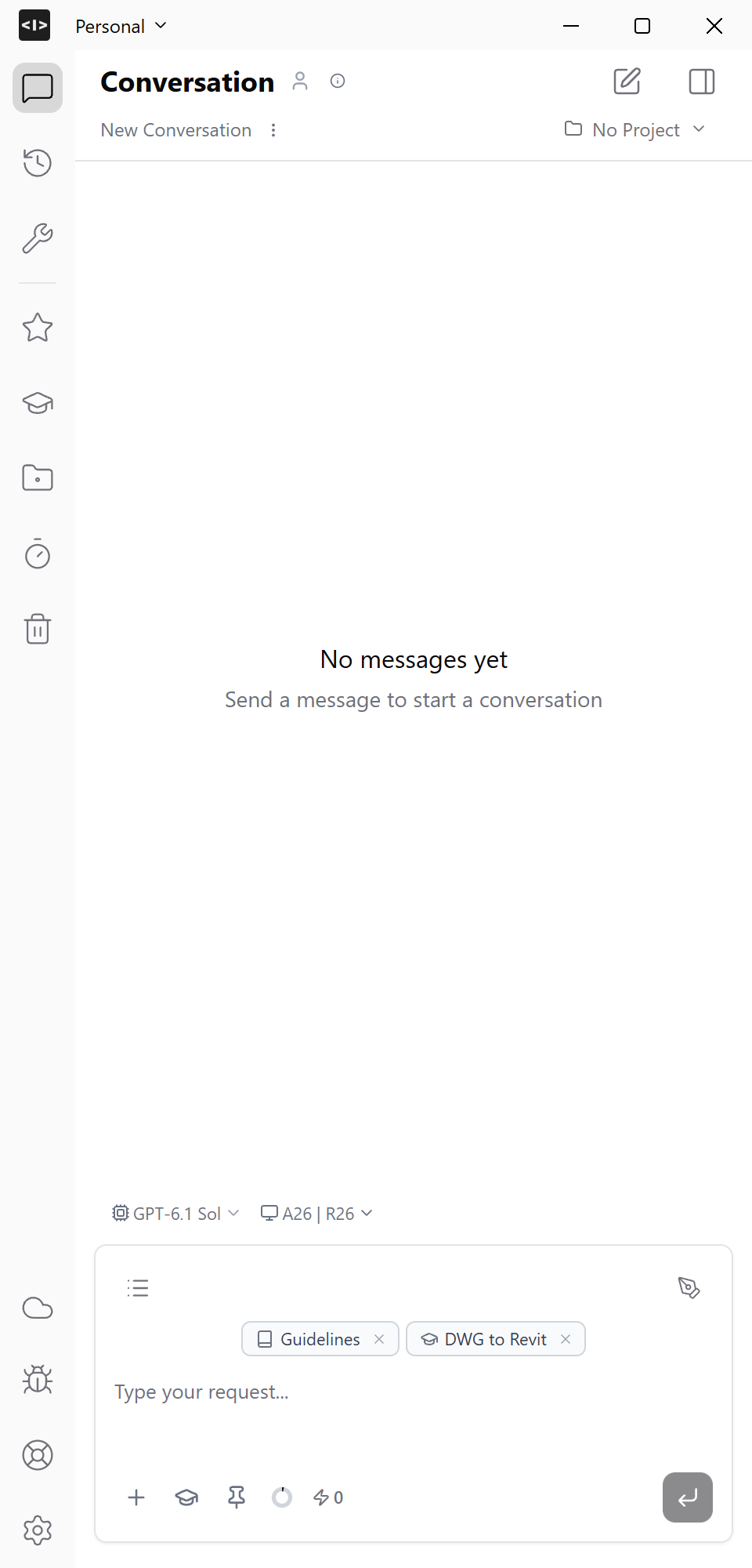
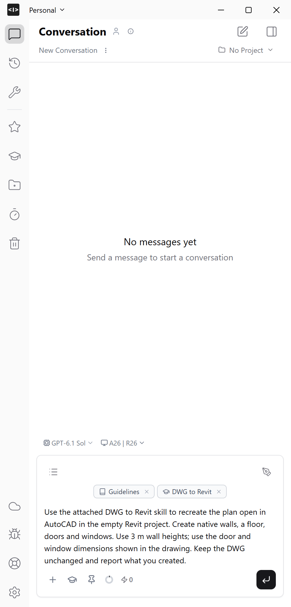
5
Follow the transfer
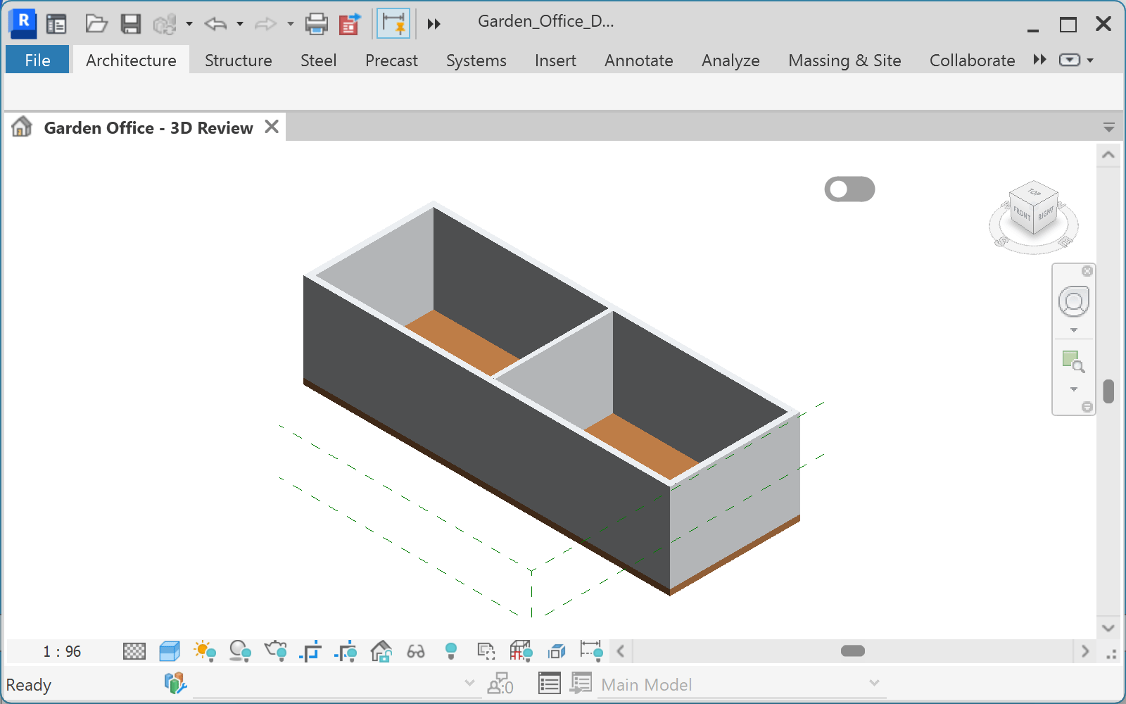
Send the request. Follow the tool calls in Studio as Ideatura reads AutoCAD and creates the model in Revit. Keep both applications visible to compare the drawing with the emerging walls and openings.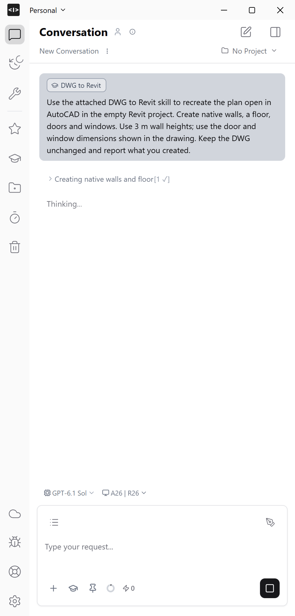
6
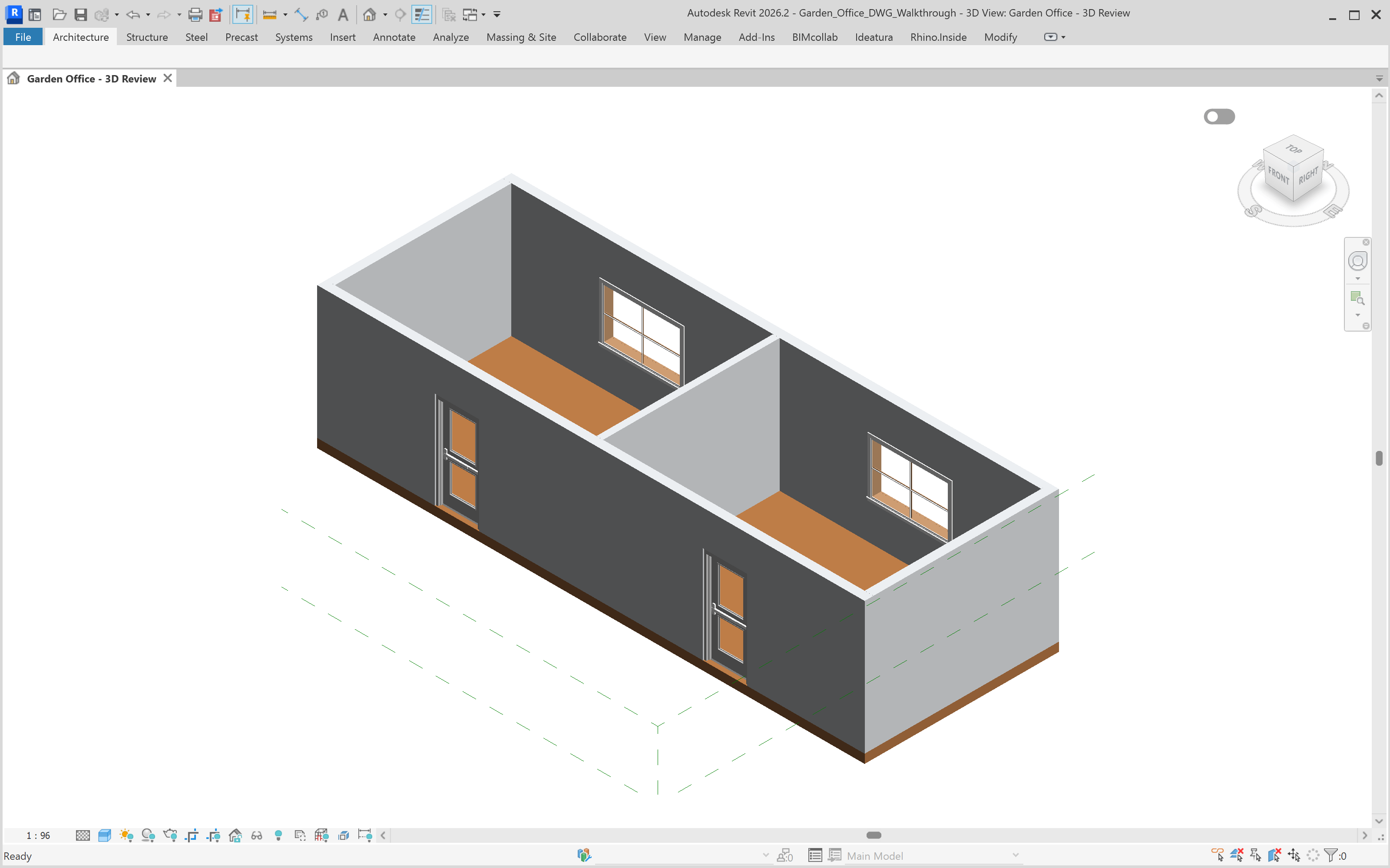
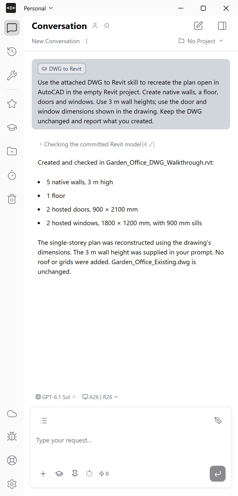
Check the model and report
Inspect the finished model in Revit. Select a wall and a hosted opening to check their categories and properties. Compare the footprint and opening positions with AutoCAD, then review Studio’s report.